
In this article, you will find the Study Notes on Circuits Analysis and Applications of Diodes, BJT, FET and MOSFET which will cover the topic as Circuit analysis of Diodes, Application of diodes, Transistors and their Characteristics, Transistor at low frequencies, Hybrid parameters and Miller's Theorem.
1. Circuit Analysis of Diodes
There are three different techniques that are used to analyse circuits that contain diodes:
- Ideal diode equation is used when the diode voltage between the breakdown voltage and the turn-on voltage of the diode
- Load line analysis can be used as long as you have an I-V characteristic for the diode
- Piecewise models are used to estimate the diode current and voltage
- The accuracy depends on the region of operation and the use of the series resistors, Rs and Rz
2. Applications of Diodes
- Radio demodulation: an AM signal consists of alternating positive and negative peaks of voltage, whose amplitude or “envelope” is proportional to the original audio signal, but whose average value is zero. The diode rectifies the AM signal, leaving a signal whose average amplitude is the desired audio signal. The average value is extracted using a simple filter and fed into an audio transducer, which generates sound.
- Power conversion: Rectifiers are constructed from diodes, where they are used to convert alternating current (AC) electricity into direct current (DC). Automotive alternators are a common example, where the diode provides better performance than the commutator of the earlier dynamo.
- Over-voltage protection: Many integrated circuits also incorporate diodes on the connection pins to prevent external voltages from damaging their sensitive transistors. Specialised diodes are used to protect from over-voltages at higher power.
- Ionising radiation detectors, Temperature measuring, Current steering etc.
3. Junction Transistor
- Both electrons and holes participate in the conduction process for bipolar devices.
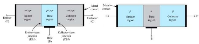
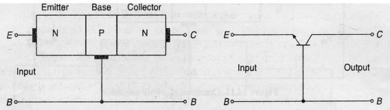
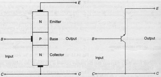
- BJT consists of two pn junctions constructed in a special way and connected in series, back to back.
- The transistor is a three-terminal device with emitter, base and collector terminals.
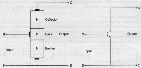
- From the physical structure, BJTs can be divided into two groups: NPN and PNP transistors.
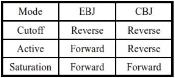
- Modes of operation:
- The two junctions of BJT can be either forward or reverse-biased.
- The BJT can operate in different modes depending on the junction bias.
- The BJT can operate in different modes depending on the junction bias.
- Switching applications utilise both the cutoff and saturation modes
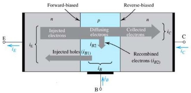
- An operation of the NPN transistor in the active mode:
- Electrons in emitter regions are injected into base due to the forward bias at EBJ.
- Most of the injected electrons reach the edge of CBJ before being recombined if the base is narrow.
- Electrons at the edge of CBJ will be swept into collector due to the reverse bias at CBJ.
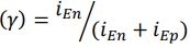
- Emitter injection efficiency
- Base transport factor
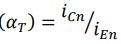
- Base transport factor
- Terminal currents of BJT in active mode:
- iE(Emitter current) = iEn(electron injection from E to B) + iEp(hole injection from B to E)
- iC(Collector current) = iCn(electron drift) + iCBO(CBJ reverse saturation current with emitter open)
- iB(Base current) = iB1(hole injection from B to E) + iB2(recombination in base region)
4. The transistor as an amplifier
- A BJT circuit with a collector resistor RC can be used as a simple voltage amplifier.
- Base terminal is used the amplifier input and the collector is considered the amplifier output.
- The voltage transfer characteristic (VTC) is obtained by solving the circuit from low to high VBE
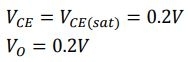
- Cutoff mode:
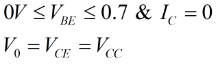
- Active mode:
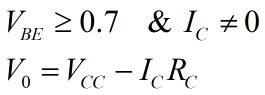
- Saturation mode:
VBE further increases
5. Transistor Configuration
Depending upon the terminals which are used as a common terminal to the input and output terminals, the transistors can be connected in the following three different configurations.
- common base configuration
- common emitter configuration
- common collector configuration
a) common base configuration
- In this configuration base terminal is connected to a common terminal.
- The input is applied between the emitter and base terminals.
- The output is taken between the collector and base terminals.
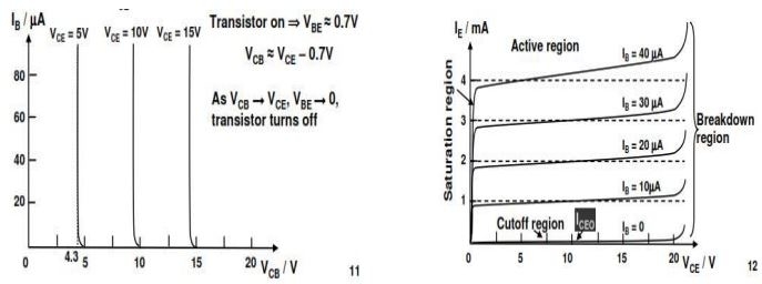
- Input characteristics: The output (CB) voltage is maintained constant and the input voltage (EB) is set at several convenient levels. For each level of an input voltage, the input current IE is recorded. IE is then plotted versus VEB to give the common-base input characteristics.
- Output characteristics: The emitter current IE is held constant at each of several fixed levels. For each fixed value of IE , the output voltage VCB is adjusted in convenient steps and the corresponding levels of collector current IC are recorded. For each fixed value of IE, IC is almost equal to IE and appears to remain constant when VCB is increased.
b) Common emitter configuration
- In this configuration, emitter terminal is connected to a common terminal
- The input is applied between the emitter and base terminals.
- The output is taken between the collector and base terminals
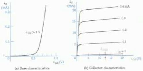
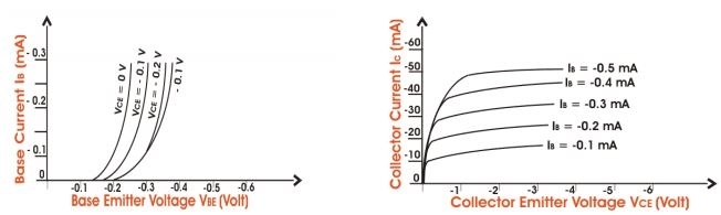
- Input characteristics: The output voltage VCE is maintained constant and the input voltage VBE is set at several convenient levels. For each level of an input voltage, the input current IB is recorded. IB is then plotted versus VBE to give the common-base input characteristics.
- Output characteristics: The Base current IB is held constant at each of several fixed levels. For each fixed value of IB, the output voltage VCE is adjusted in convenient steps and the corresponding levels of collector current IC are recorded. For each fixed value of IB, IC level is Recorded at each VCE step. For each IB level, IC is plotted versus VCE to give a family of characteristics.
c) Common collector configuration
- In this configuration, collector terminal is connected to a common terminal.
- The input is applied between the base and collector terminals.
- The output is taken between the emitter and collector terminals.
- Input characteristics: The common-collector input characteristics are quite different from either common base or common-emitter input characteristics. The difference is due to the fact that the input voltage (VBC) is largely determined by (VEC) level.
- Output characteristics: The operation is much similar to that of C-E configuration. When the base current is ICO, the emitter current will be zero and consequently no current will flow in the load. When the base current is increased, the transistor passes through active region and eventually reaches saturation. Under the saturation conditions all the supply voltage, except for a very small drop across the transistor will appear across the load resistor
6. Transistor at low frequencies
The transistor can be employed as an amplifying device, that is, the output ac power is greater than the input ac power. The factor that permits an ac power output greater than the input ac power is the applied DC power. The amplifier is initially biased for the required DC voltages and currents. Then the ac to be amplified is given as input to the amplifier. If the applied ac exceeds the limit set by dc level, clipping of the peak region will result in the output. Thus, proper (faithful) amplification design requires that the dc and ac components be sensitive to each other’s requirements and limitations. The superposition theorem is applicable for the analysis and design of the dc and ac components of a BJT network, permitting the separation of the analysis of the dc and ac responses of the system.
- BJT Transistor modelling:
- A model is an equivalent circuit that represents the AC characteristics of the transistor.
- A model uses circuit elements that approximate the behaviour of the transistor.
- There are two models commonly used in small signal AC analysis of a transistor:
- re model
- Hybrid equivalent model
- Two port device and hybrid model:
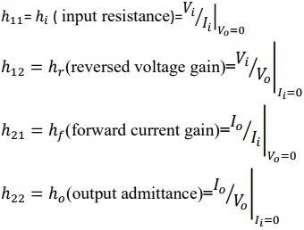
- For the hybrid equivalent model, the parameters are defined at an operating point.
- The quantities ℎie, ℎre, ℎfe, and ℎoe are called hybrid parameters and are the components of a small – signal equivalent circuit.
- The description of the hybrid equivalent model will begin with the general two port system.
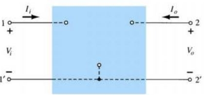
![]()
- The four variables ℎ11, ℎ12, ℎ21 and ℎ22 are called hybrid parameters (the mixture of variables in each equation results in a “hybrid” set of units of measurement for the h – parameters).
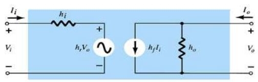
7. Analysis of transistor amplifier using h-parameter
For analysis of transistor amplifier, we have to determine the following terms:
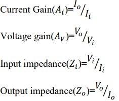
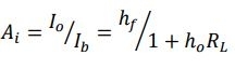
- Current Gain: the current gain will reduce to the familiar result of Ai= ℎf if the factor ℎoRL is sufficiently small compared to 1.
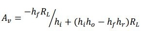
- Voltage gain: In this case, the familiar form
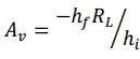 of will return if the factor
 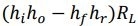 is sufficiently small compared to hi.
- Input impedance:
![]()
- Output impedance:

8. Miller’s theorem and its dual
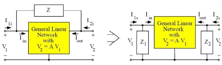
- The introduction of an impedance that connects amplifier input and output ports adds a great deal of complexity in the analysis process. One technique that often helps reduce the complexity in some circuits is the use of Miller's theorem. Miller's theorem applies to the process of creating equivalent circuits. This general circuit theorem is particularly useful in the high-frequency analysis of certain transistor amplifiers at high frequencies.
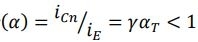
- Miller's Theorem generally states: Given any general linear network having a common terminal and two terminals whose voltage ratio, with respect to the common terminal, is given by
![]()
- If the two terminals of the network are then interconnected by impedance, Z, an equivalent circuit can be formed. This equivalent circuit consists of the same general linear network and two impedances; each of which shunts a network terminal to common terminal. These two impedances have value
![]()
Agr psnd aaye toh please comment section m jarur btaye ki kesa lga apko kya ye use full tha ya nhi
Comments
Post a Comment
Thanks for reading my Blogs or articles